Contents:
- DHT11 on Raspberry Pi
- Temperature and Humidity Logs
- SPI Interface
- Nokia 5110 LCD Python Library (SPI)
- Dispaying Temperature and Humidity on Nokia LCD
DHT11 on Raspberry Pi:
 The DHT11 is basic digital temperature and humidity sensor. Internally it uses thermistor and a capacitive humidity sensor to measure surrounding atmosphere. It generates a digital signal on the data pin of raspberry pi device. It is easy to use and we can read new data recordings once every 2 seconds.
Wiring up DHT11 sensor on Raspberry Pi:
This DHT11 sensor has 4-pins. We can connect to any GPIO (General Purpose Input and Output) port on Raspberry Pi device. Here we are connecting to GPIO4(Input/Output. Or provides a master clock output (GPCLK0) to external circuits) of raspberry pi from the 2nd pin wi of DHT11.
Following figure represents the general wiring diagram of DHT11 temperature and humidity sensor to Raspberry Pi IO.

- Connect 1st pin of DHT to 3V (pin#1) of Raspberry Pi device.
- Connect 2nd pin of DHT to GPIO#4 of RPi and parallelly connect 2nd pin to a 470 Ohms resistor (if it doesn't work use 10K Ohms resistor).
- Other end of resistor should be connected to 3V (pin#1).
- Finally, connect 4th in of DHT to any one of GND (Groud) on Raspberry Pi device.
Programming to use Temperature and Humidity Sensor in Python:
To start and use the DHT sensor on raspberry pi we need to handle it through GPIO pins which can be accessed using programming. Here we are using Python, and to use the DHT on Raspberry Pi, first we need to install required packages available in python and their dependencies.
Setting up DHT-Python Packages:

Serial Peripheral Interface(SPI) is a serial data protocol which is used by small electronic devices and micro-controllers to transfer and exchange information. In SPI, the term serial represents that each bit in binary number is sent one at a time, on the same wire. Example: If we consider number 251, in binary system it is 11111011. These SPI devices divided into two categories: one is masters and the other is slaves.

To connect Nokia 5110 LCD to a Raspberry Pi is simple because these boars use the same power consumption 3.3V. There is no need to use a level converter chip.
In general, we need to connect the LCD's SCLK, DIN and CS pins to the board's SPI pins, and the LCD's RST and D/C pins to two free digital I/O pins. With this setup we can use the fast hardware SPI support built into our Raspberry Pi board. The library also supports software SPI on any 5 digital I/O pins (SCLK, DIN, CS, RST, D/C).
To install the dependencies, follow the below steps:
To start and use the DHT sensor on raspberry pi we need to handle it through GPIO pins which can be accessed using programming. Here we are using Python, and to use the DHT on Raspberry Pi, first we need to install required packages available in python and their dependencies.
Setting up DHT-Python Packages:
- Open LXTerminal and login as super user: 'sudo su'.
- Enter the following commands: git clone https://github.com/adafruit/Adafruit_Python_DHT.git
- cd Adafruit_Python_DHT
- sudo apt-get update
- sudo apt-get install build-essential python-dev python-openssl
- sudo python setup.py install

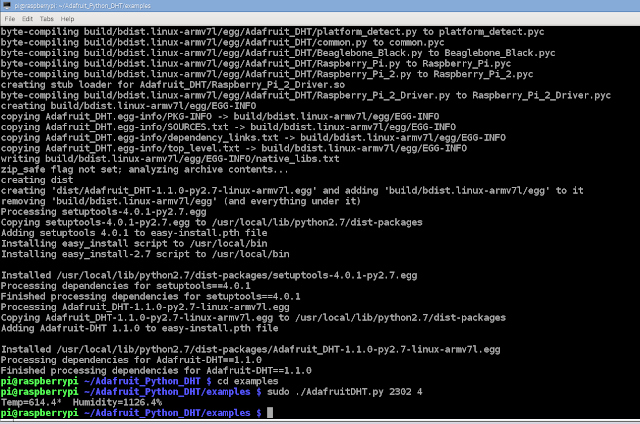
The necessary installation part is done. Now, we can test the temperature and humidity sensor as follows:
- cd examples
- sudo ./AdafruitDHT.py 2302 4

Output shows: Temp=614.4* Humidity=1126.4%
Temperature and Humidity Logs:
To create logs on readings of temperature and humidity by DHT sensor;


Finally, run this google_spreadsheet.py program. You will see the updates on your spreadsheet on google, as below.
- First we need to create a spreadsheet in Google Docs.
- After spreadsheet created, delete all the rows except the first row to label them with the headings (column names).
- Get OAuth2 credentials;
- Go to https://console.developers.google.com/start (Google Developers Console).
- Create a new project (created 'DHTLogs').
- Select 'Enable and Manage APIs', under 'Google Apps APIs' select 'Drive API'.

- Click on the 'Enable API' button. Now you will see the following alert.


- Click on the 'Go to Credentials' button and select 'Service Account Key'.
- In the following page select 'Compute Engine default service account' and click on 'Create'.

- It automatically downloads JSON file with credentials information in it.
- To install oauth2: 'pip install --upgrade oauth2client' and then 'pip install PyOpenSSL'.
- Now, You need to run the below code to authenticate your credentials.
import json
import gspread
import Adafruit_DHT
from oauth2client.client import SignedJwtAssertionCredentials
DHT_TYPE = Adafruit_DHT.DHT11
DHT_PIN = 4
GDOCS_OAUTH_JSON = 'DHTLogs-3736f2d30591.json'
GDOCS_SPREADSHEET_NAME = 'DHT Humidity Logs'
json_key = json.load(open('DHTLogs-3736f2d30591.json'))
scope = ['https://spreadsheets.google.com/feeds']
credentials = SignedJwtAssertionCredentials(json_key['client_email'], json_key['private_key'].encode(), scope)
gc = gspread.authorize(credentials)
wks = gc.open("DHT Humidity Logs").sheet1
You are all set with OAuth2 Credentials. Now, go to Adafruit_Python_DHT/examples folder and open google_spreadsheet.py, and make the following changes;
- Go to google sheets and click on 'Share' to a client email which you have got from the JSON file.
- DHT_TYPE = Adafruit_DHT.DHT11
- DHT_PIN = 4
- GDOCS_OAUTH_JSON = 'DHTLogs-3736f2d30591.json'
- GDOCS_SPREADSHEET_NAME = 'DHT Humidity Logs'
Finally, run this google_spreadsheet.py program. You will see the updates on your spreadsheet on google, as below.

SPI Interface
Serial Peripheral Interface(SPI) is a serial data protocol which is used by small electronic devices and micro-controllers to transfer and exchange information. In SPI, the term serial represents that each bit in binary number is sent one at a time, on the same wire. Example: If we consider number 251, in binary system it is 11111011. These SPI devices divided into two categories: one is masters and the other is slaves.
- Master - the device that starts communication.
- Slave - receives instructions from master and does what the master says.

In SPI devices, master can communicate with many slaves, but usually one at a time.
To connect with SPI devices we need to have four necessary pins on Raspberry Pi device.
- MOSI (Master Output, Slave Input) - Master uses this pin (line) to send the information to slave.
- MISO (Master Input, Slave Output) - Master uses this line to read the information from slave.
- SCLK (Serial Clock) - Each bit is read on the edge of the clock signal.
- SS (Slave Select) - We have two different pins on RPi- CE0 & CE1. Use one on these for each slave device is the circuit. By using this line, master indicates which slave device should respond to the given instructions.
Enabling SPI on the Raspberry Pi:
Generally, we can use any of the GPIO Input/Output pins for SPI, because it is only the matter of reading input, and bringing pins high and low. On the other hand, five of the Raspberry Pi's GPIO pins have specialized alternative features(uses) for communicating over SPI. By using these pins you can use built-in libraries and tools instead of writing as much code. Those SPI pins on the GPIO header are:
- MOSI - pin#19
- MISO - pin#21
- SCLK - pin#23
- CE0(SS) - pin#24
- CE1(SS) - pin#26
In default mode, SPI functions of above pins are disabled in Raspbian(OS). To enable them we need to do the following steps:
- Open LXTerminal and enter the command: 'sudo raspi-config'.
- Select 'Adavanced Options', by moving down arrow key and press Enter.
- Select 'SPI' and press Enter.
- Select 'Yes' and press Enter to continue.
- Now, select 'Finish' option and press Enter.
- Type the following command: 'sudo nano /etc/modules'.
- Now you will see a file editor. Go to end of the file and add the following line: 'spi-dev'.
- Press Ctrl + O and press Enter.
- Press Ctrl + X to exit from file editor.
- To shutdown pi enter the following command: 'sudo shutdown -r now'.
When the Pi restarts, SPI modules load automatically.
Using SPI from Python3:
To access SPI using Python, we need to install built-in libraries of python3-dev and module for Python that enables SPI devices accessible. Do the following steps:
- Open LXTerminal and type command: 'sudo apt-get install python3-dev'.
- Enter command: 'git clone https://github.com/doceme/py-spidev'.
- Enter: 'cd py-spidev'.
- To install: 'sudo python3 setup.py install'.
Now, we are setup with all installations to use SPI devices and to access them through Python3.
Nokia 5110 LCD Python Library (SPI):
Nokia 5110 Display is an inexpensive graphical display that's easy to use with modern linux-based development board like Raspberry Pi. To enable it to use on RPi, we have built-in library called Adafruit Nokia LCD Python library (http://adafru.it/dvf). This library allows you to connect the Nokia LCD to a Raspberry Pi or Beaglebone Black and
display graphics using the Python programming language.

Wiring - Nokia 5110 LCD on Raspberry Pi:
To connect Nokia 5110 LCD to a Raspberry Pi is simple because these boars use the same power consumption 3.3V. There is no need to use a level converter chip.
In general, we need to connect the LCD's SCLK, DIN and CS pins to the board's SPI pins, and the LCD's RST and D/C pins to two free digital I/O pins. With this setup we can use the fast hardware SPI support built into our Raspberry Pi board. The library also supports software SPI on any 5 digital I/O pins (SCLK, DIN, CS, RST, D/C).
To install the dependencies, follow the below steps:
- Open LXTerminal and enter the following commands.
- sudo apt-get install python-pip python-dev build-essential
- sudo pip install RPi.GPIO
- sudo apt-get install python-imaging
- sudo apt-get install git
- git clone https://github.com/adafruit/Adafruit_Nokia_LCD.git
- cd Adafruit_Nokia_LCD
- sudo python setup.py install
Now, you should
see the files /dev/spidev0.0 and /dev/spidev0.1 are available.
Dispaying Temperature and Humidity on Nokia LCD:
By combining all the above learned concepts, I want to display the readings of DHT11 Temperature and Humidity Sensor on Nokia 5110 LCD.
Below video shows;
Below video shows;
- Temperature and Humidity updates on LCD screen.
- If humidity is high - Red LED
- If humidity is low - Yellow LED
Following python code enables me to display the readings on LCD as well as LED signalling to indicate high(red) and low(yellow) humidity in the surrounding air.
--------------------------------------------------
Display2.py |
--------------------------------------------------
import time
import sys
import RPi.GPIO
import Adafruit_DHT
import Adafruit_Nokia_LCD as LCD
import Adafruit_GPIO.SPI as SPI
import Image
import ImageDraw
import ImageFont
# Raspberry Pi hardware SPI config:
DC = 23
RST = 24
SPI_PORT = 0
SPI_DEVICE = 0
# Hardware SPI usage:
disp = LCD.PCD8544(DC, RST, spi=SPI.SpiDev(SPI_PORT, SPI_DEVICE, max_speed_hz=4000000))
disp.begin(contrast=60)
disp.clear()
disp.display()
image = Image.new('1', (LCD.LCDWIDTH, LCD.LCDHEIGHT))
draw = ImageDraw.Draw(image)
draw.rectangle((0,0,LCD.LCDWIDTH,LCD.LCDHEIGHT), outline=255, fill=255)
font = ImageFont.load_default()
#LED-GPIO setup
RPi.GPIO.setmode(RPi.GPIO.BCM)
RPi.GPIO.setup(2,RPi.GPIO.OUT)
RPi.GPIO.setup(3,RPi.GPIO.OUT)
RPi.GPIO.output(3, False)
RPi.GPIO.output(2, False)
while True:
sensor_args = { '11': Adafruit_DHT.DHT11,
'22': Adafruit_DHT.DHT22,
'2302': Adafruit_DHT.AM2302 }
if len(sys.argv) == 3 and sys.argv[1] in sensor_args:
sensor = sensor_args[sys.argv[1]]
pin = sys.argv[2]
else:
print 'usage: sudo ./Adafruit_DHT.py [11|22|2302] GPIOpin#'
print 'example: sudo ./Adafruit_DHT.py 2302 4 - Read from an AM2302 connected to GPIO #4'
sys.exit(1)
humidity, temperature = Adafruit_DHT.read_retry(sensor, pin)
if humidity is not None and temperature is not None:
print 'Temp={0:0.1f}* Humidity={1:0.1f}%'.format(temperature, humidity)
draw.text((1,1), 'Temp={0:0.1f}*'.format(temperature, humidity), font=font)
draw.text((1,30), 'Humid={0:0.1f}%'.format(humidity, temperature), font=font)
# Display image.
disp.image(image)
disp.display()
if humidity > 1152:
RPi.GPIO.output(3, False)
RPi.GPIO.output(2, True)
else:
RPi.GPIO.output(3, True)
RPi.GPIO.output(2, False)
time.sleep(2)
disp.clear()
disp.display()
else:
print 'Failed to get reading. Try again!'
sys.exit(1)
--------------------------------------------------
Display2.py |
--------------------------------------------------
import time
import sys
import RPi.GPIO
import Adafruit_DHT
import Adafruit_Nokia_LCD as LCD
import Adafruit_GPIO.SPI as SPI
import Image
import ImageDraw
import ImageFont
# Raspberry Pi hardware SPI config:
DC = 23
RST = 24
SPI_PORT = 0
SPI_DEVICE = 0
# Hardware SPI usage:
disp = LCD.PCD8544(DC, RST, spi=SPI.SpiDev(SPI_PORT, SPI_DEVICE, max_speed_hz=4000000))
disp.begin(contrast=60)
disp.clear()
disp.display()
image = Image.new('1', (LCD.LCDWIDTH, LCD.LCDHEIGHT))
draw = ImageDraw.Draw(image)
draw.rectangle((0,0,LCD.LCDWIDTH,LCD.LCDHEIGHT), outline=255, fill=255)
font = ImageFont.load_default()
#LED-GPIO setup
RPi.GPIO.setmode(RPi.GPIO.BCM)
RPi.GPIO.setup(2,RPi.GPIO.OUT)
RPi.GPIO.setup(3,RPi.GPIO.OUT)
RPi.GPIO.output(3, False)
RPi.GPIO.output(2, False)
while True:
sensor_args = { '11': Adafruit_DHT.DHT11,
'22': Adafruit_DHT.DHT22,
'2302': Adafruit_DHT.AM2302 }
if len(sys.argv) == 3 and sys.argv[1] in sensor_args:
sensor = sensor_args[sys.argv[1]]
pin = sys.argv[2]
else:
print 'usage: sudo ./Adafruit_DHT.py [11|22|2302] GPIOpin#'
print 'example: sudo ./Adafruit_DHT.py 2302 4 - Read from an AM2302 connected to GPIO #4'
sys.exit(1)
humidity, temperature = Adafruit_DHT.read_retry(sensor, pin)
if humidity is not None and temperature is not None:
print 'Temp={0:0.1f}* Humidity={1:0.1f}%'.format(temperature, humidity)
draw.text((1,1), 'Temp={0:0.1f}*'.format(temperature, humidity), font=font)
draw.text((1,30), 'Humid={0:0.1f}%'.format(humidity, temperature), font=font)
# Display image.
disp.image(image)
disp.display()
if humidity > 1152:
RPi.GPIO.output(3, False)
RPi.GPIO.output(2, True)
else:
RPi.GPIO.output(3, True)
RPi.GPIO.output(2, False)
time.sleep(2)
disp.clear()
disp.display()
else:
print 'Failed to get reading. Try again!'
sys.exit(1)
Learning Scope:
- DHT11 setup on Raspberry Pi and How to use it.
- Logging readings of sensor in a google spreadsheet.
- SPI Interface setup on Raspberry Pi.
- Nokia 5110 LCD connection on Raspberry Pi.
- Python Programming: Displaying sensor readings on Nokia LCD.
- LED setup for high and low humidity indications.
No comments:
Post a Comment